When Cass Gilbert designed the Palace of Fine Arts, a classical limestone edifice, for the 1904 World’s Fair in St. Louis, it was the only structure intended to remain once that centennial celebration of the Louisiana Purchase ended. It still stands today as home to another palace of the arts: the St. Louis Art Museum.
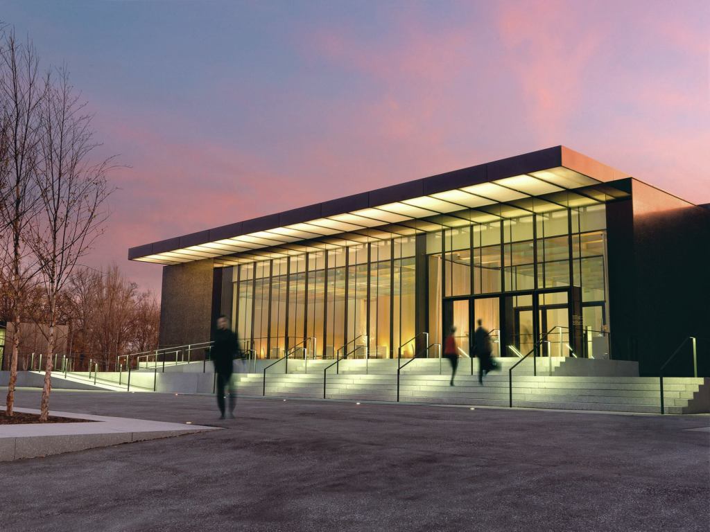
After nearly a century in its historic home, the museum, needing more space, decided to expand on its Art Hill site in Forest Park. The museum board turned to London-based architect David Chipperfield, Hon. FAIA, to create a new wing that would “not compete with, nor take away from, the historic stature of the main building,” says Roger McFarland, AIA, group vice president at St. Louis–based HOK, which served as the associate architect.
The result is a 200,000-square-foot addition that hides parking for 300 cars underneath a single level incorporating 21 new galleries and a new café. The structure is largely composed of polished concrete with local river aggregate. The material continues in the building’s unifying formal element: a 40,000-square-foot concrete-grid ceiling canopy.
As one would expect of Chipperfield, the geometry of the grid slab is rigorous: 5-foot-by-10-foot voids, dubbed coffers, are partitioned by 1-foot-thick concrete ribs. The 4-foot-tall slab was poured on site after the vertical structure of columnar supports and concrete exterior walls (which serve as shear walls) was already in place. To execute what would essentially be an aerial pour, the team built a temporary plywood platform, which it called “the dance floor,” 18 feet above the floor slab. Disrupted only by the column caps that would connect with the ceiling slab, the platform formed the base for the formwork.
While the addition’s exterior walls would undergo polishing to achieve the final finish, the design team wanted the “materiality of the coffers to be as natural as possible,” McFarland says. A series of small- and full-scale mock-ups of the coffers (more than 40 were created over the course of the project) helped the designers determine which mix of concrete would work best. After testing, the decision was made to use self-compacting concrete, which, when mixed, had “the consistency of pancake batter,” McFarland says, but would result in a smooth surface and sharp corners—important details for the largely exposed final result.
Millwork-quality boxes, each the dimension of a single coffer and filled with Styrofoam, served as formwork. Once the pour was complete, the tops of the boxes were removed and the walls broken out from inside to leave only the pristine concrete structure behind.
The concrete for the slab—all 1,600 cubic yards of it—was poured in 11 sections, each consisting of up to 28 truckloads of concrete. First, the construction team tied together the grids of rebar (assembled above the formwork for the slab) and dropped them into the gridded voids. When the concrete trucks arrived site, “it was a ballet,” McFarland says.“It was fun to watch these things come and go.” The longest pour was the first, which lasted two hours.
The final result was a continuous structure that was left to cure in the elements for several months while the rest of the building was constructed; UV exposure lightened the concrete to its final, pale color. To enclose the addition, a metal roof system was installed roughly 3 feet above the coffers, leaving room for air returns, plenum barriers, lighting systems, and other infrastructure. While many areas, including the café and temporary exhibition galleries, have an opaque ceiling over the coffers, the permanent exhibition galleries and the public spaces have skylights that allow natural daylight to filter in.
The grid slab is expressed throughout the interior, with gallery walls mimicking the 1-foot thickness of the ribs and concealing the structural columns. Air distribution grilles in the floor run the length of the galleries and mimic the geometry of the grid above. “It sets up the rhythm of the building,” McFarland says. “Every wall is tied to it. Every mechanical grille is tied to it.”
McFarland says that, overall, the ceiling system contributed to a trompe l’oeil effect, in which the addition can appear deceptively small next to Gilbert’s limestone pile and the wooded surroundings of Forest Park. “Visitors are going to be amazed by how large the galleries feel on the inside after their perception of the size of the building on the outside,” he says. “This system of coffers removes scale. You want to look up, yet you’re drawn to the simplicity of the structure.”